The structure and development trend of large-size direct-lit backlight
Oct 11, 2021
Liquid crystal display is a kind of non-self-luminous display technology, which must use backlight to display images. Therefore, the development of backlight is very important to the performance of liquid crystal display. However, as the demand for large-scale liquid crystal display continues to grow, the proportion of the cost of traditional backlight It is also increasing. Backlights are making efforts to improve their lightness, thinness, low power consumption, high brightness, and low cost.
1 Introduction to large-size LCD panel and backlight
Liquid crystal displays display information through the modulation of light by liquid crystals. Development opportunities and technological innovations are closely related to the improvement of backlights, including the dynamic control of cold cathode fluorescent tubes (CCFL), external electrode fluorescent lamps (EEFL), and planar fluorescent lamps. The development of FFL (FlatFluorescent Lamp), Light Emitting Diode (Light Emitting Diode) backlights, etc.
1.1 LCD panel
LCD panel is mainly composed of color filter (ColorFilter), backlight module (Backlight), driver chip (IC), compensation film and polarizer (Retardation film and Polarizer), ITO glass substrate (ITO Substrate), orientation film (PI film) , Control circuit and other components.
1.2 Backlight module
The backlight module is assembled by the light source, lampshade, reflector, LGP (light guideplate), diffuser, BEF (Brightness Enhancement Film) and outer frame. Among them, the light source includes cold cathode fluorescent tube CCFL, hot cathode fluorescent tube, HCFL (HotCathode Fluorescent Lamp) external electrode fluorescent lamp EEFL, light-emitting diode LED, flat fluorescent FFL, field emission backlight FE (Field Emission Backlight), etc.
The backlight light source emits light and enters the light guide plate. After spreading, it is emitted from the front at a certain angle and is evenly distributed in the light-emitting area, and then passes through the diffuser plate and the brightness enhancement film to gather the light within the viewing angle range of the liquid crystal display.
2 The main structure of the backlight
LCD applications are different, leading to differences in related product characteristics, such as size, brightness, response speed, resolution, and color saturation. Generally speaking, according to the position of the lamp, the following structures are roughly adopted:
2.1 Edge Backlight
The LGP (Light Guide Plate) guides the direction of light, improves the brightness of the panel and controls the brightness evenly.
The light source of Edge Backlight is generally on the side of the light guide plate. The light source has straight, L-shaped, and U-shaped CCFL tubes according to the form of the light guide plate and optical requirements. The CCFL has no heat dissipation problem on the side, but the amount of light provided by the CCFL passes through the light guide plate, diffuser film, polarizing film, liquid crystal layer, color filter and other multi-layer components, the efficiency is quite low.
2.2 Bottom Lighting
When used in large-size displays, the edge-lit structure cannot have advantages in weight, power consumption, and brightness. Therefore, a direct-lit structure without a light guide plate and a light source placed directly below has been developed. The direct type backlight has fewer parts and the overall luminous efficiency is higher than that of the edge type. Its brightness, uniformity, color saturation, etc. basically meet the requirements. The larger the panel, the longer the tube, and the higher the uniformity requirements of the tube itself, we had to increase the diffuser plate, but the brightness was insufficient, so we continued to increase the tube. Therefore, the larger the size, the higher the cost of the backlight, which is almost linear. However, with the increase of lamps, the power consumption has also increased to 90% of the liquid crystal display, and the heat dissipation problem has become increasingly serious.
3 Light source classification of direct backlight
The light source system determines the brightness and uniformity of the display. The luminous sources used in LCDs include CCFL, HCFL, EEFL, FFL, LED, FE, etc. Among them, CCFL has the characteristics of high brightness, high efficiency, long life, high color rendering, etc. , And its cylindrical structure is easy to combine with light reflecting elements to form a thin plate-shaped lighting device, so CCFL is still the mainstream at present, but it is generally believed that white light LEDs will be the application trend.
3.1 CCFL
As the light source, cold cathode tubes have developed with the rapid development of light guide plates. The light guide plates have become thinner and thinner, and cold cathode tubes with a diameter of about 2.6mm have become the mainstream.
The high-voltage electrode of CCFL excites electrons, electrons collide with Ne and Ar atoms, absorb energy, heat up, high-energy Ne and Ar release energy, hit Hg (Xe can also be used) to absorb energy, H g releases ultraviolet light λ=2 5 3.7nm, hits the phosphor, and emits visible light. Electron emission from the electrode is not thermionic emission, so it is called cold cathode tube. Since the electrode does not have a filament, the electrode can be made thin, which has the advantages of high efficiency, stability and reliability, but it has to be used with reflector, diffusion film, etc., and the structure is complicated. 32" uses 12 tubes. When it reaches 37", the number of tubes increases to about 20. The cost increases too fast, approaching more than 40% of the entire system. Moreover, each tube needs to be driven separately, and the response speed is slow. The saturation is only about 72%, and at the same time, the use of mercury brings potential environmental problems.
3.2 LED
Its advantages are low voltage, lightness, mercury-free, long life, etc., and its light source spectrum is purer than the light produced by phosphors as luminescent materials. It is currently the only option that reaches and exceeds NTSC 100% color saturation. Its unit of power consumption can obtain higher brightness, and its response speed is 3 times faster than that of CCFL, which can give high added value to the liquid crystal panel. Three kinds of RGB LEDs are used as the light source, which can be switched and lit in sequence, which can replace the expensive color filter CF. However, the price is relatively expensive and the power consumption is relatively large.
3.3 Hybrid
The LED hybrid backlight technology can greatly improve the display quality of LCD TVs. It adopts AFLC area-focused Luminance Controllable technology, which can analyze image data by itself and automatically adjust the brightness of specific parts to make the bright parts brighter and darker. The part is darker.
Hybrid LED backlit liquid crystal display, color saturation can reach 110%, contrast ratio can reach 10000: response speed below 1.8ms, using IPS wide viewing angle technology, up and down, left and right viewing angles up to 178 degrees. The hybrid backlight display using LED and fluorescent light can achieve 105% color saturation, which is 45% higher than that of the display using fluorescent light backlight, and the cost is only about 60% of that of LED backlight.
The display characteristics and cost advantages of the field emission backlight FE FE backlight will also have a place in the future.
Organic LED OLED This is a future display, but it can also be used as a backlight. It simplifies the optical structure of the backlight and has a low driving voltage. However, the current problems are short life span, low efficiency, low temperature sensitivity, and high price. .
4 Backlight and other components
4.1 Light guide plate (only applicable to side-light type backlight)
The shape and material of the light guide plate determine the brightness and distribution of the emitted light source.
The most common is the printed light guide plate, based on the distance from the light source, using highly reflective light source materials, such as SiO2 and TiO2 distributed on the bottom surface of the light guide plate, using the nature of the printing material to absorb and diffuse, destroying the internal propagation caused by total reflection. Distribute the light evenly from the front.
Non-printing type includes injection molding light guide plate, using etching, cutting method, sandblasting method for reprocessing, and diffusion type.
The etching type designs the printing points on the mold, and the cutting type cuts long grooves on the front of the duct plate. Sandblasting also forms a rough surface distribution on the mold core. The diffusion method directly injects PMMA into the duct plate. In terms of brightness, the etched light guide plate is not as good as the printed light guide plate.
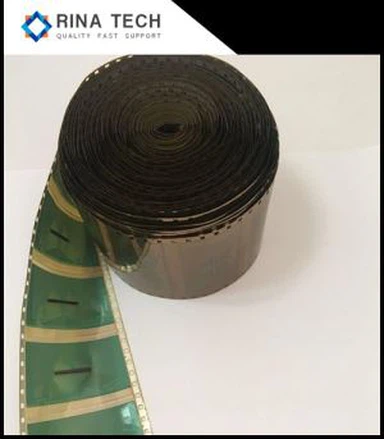
4.2 Reflector
The reflective plate of the edge-lit backlight module is placed at the bottom of the light guide plate to reflect the light leaking from the bottom surface back into the light guide plate to prevent the light source from leaking out to increase the efficiency of light use; while the direct type backlight module places the reflective plate on the light guide plate. The bottom surface of the light box may be pasted on it, and the light beam reflected by the diffuser plate is reflected from the bottom of the light box back to the diffuser plate for use.
Commonly used metal reflective film, the better the metal conductivity, the shallower the penetration depth, the higher the reflectivity, so the metal reflective film is made of high-conductivity gold, silver and copper.
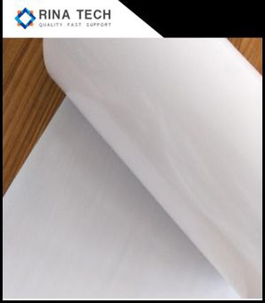
4.3 Diffuser
Generally, the traditional diffusion film is to add chemical particles to the diffusion film base material as scattering particles. The particles of the existing diffusion plate are dispersed between the resin layers, so the light will continue to be refracted between the two layers when passing through the diffusion layer. When passing through media with different rates, the light will also undergo a lot of refraction, reflection and scattering, so as to achieve the effect of optical diffusion. The diffuser/sheet provides a uniform surface light source, while also supporting other diaphragms.
Due to the nature of the chemical particles of the material, it will inevitably cause light absorption and light scattering chaos. For a fixed distance observer, part of the light intensity will be wasted. In addition, the chemical process is time-consuming, and the required production cost is relatively high. In addition, there are many diffusers made of other materials and processes.
4.4 BEF Bright Enhanced Film (Prism Film) Bright Enhanced Film
The directivity of the light is poor after diffusion, and the brightness enhancement film must be used to correct the direction of the light. It achieves the purpose of condensing light and improving the front brightness through light refraction and reflection. Polyester or polycarbonate is used as the material, and the surface structure is general. It is a prismatic cylinder or semi-cylinder, which can bend a large angle of light to a more positive angle, reduce the light distribution, achieve positive concentration, and increase the brightness of the overall backlight module by 60%~100%. Usually one The backlight will use two brightness-enhancing films, which are perpendicular to each other to increase brightness.
The light that is close to the vertical will be totally reflected after entering the light-enhancing film, and return to the bottom reflector again, and then back again. After a certain path, there is bound to be a certain amount of attenuation. Therefore, for the original light with a small angle, it will be There will be no substantial help.
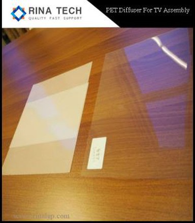
4.5 Polarization conversion film (P-S converter)
In the existing LCD panel design, the light source module filters out the S-ray parallel light, allows the P-ray light source to pass, and uses a single polarized light to drive or illuminate the LCD panel, so the light passes through the polarized light before entering the LCD panel The polarizing plate will absorb the energy in a certain polarization direction, and the light generated by the cold cathode tube is non-polarized light. When passing through the first polarizing plate, more than half of the light energy will be absorbed, making the light The use efficiency is very poor. The polarization conversion film is used, and its function is to convert the polarization state of the light source. The reflective polarizer is used to separate the light that can pass through and the light that cannot pass through the LCD polarizer, and then the light reflected by the reflector is converted into usable polarized light to achieve the purpose of improving brightness.
A DBEF (Dual BEF) with a reflective polarization conversion film, which integrates the functions of light collection and polarization conversion. In addition to the improvement of the front brightness, the brightness of the large viewing angle is also improved.
The structure principle of DBEF The above are the commonly used components. The arrangement of the diaphragms is also slightly different in the edge type backlight and the direct type backlight.
5 Conclusion
Edge-lit backlights are mainly used in desktop computers and notebook computer monitors. LCD TVs use direct-lit backlights. Currently, CCFL is still the main source. However, with the increase of panels, its cost and light utilization efficiency are not ideal. An easier alternative in the short term is the EEFL backlight.
The color saturation and luminous efficiency of LEDs are still improving, and will become the mainstream if solved.